 EEWeb Electronics Forum

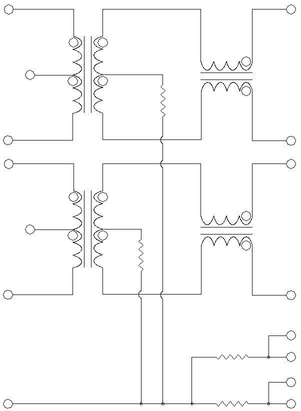
The above picture is the internal schematic representation of part number J0011D21B RJ45 jack from Pulse Inc. @ www.pulseeng.com.
I have came across this component during me design stage of Ethernet controller.
Unfortunately, my schematic software (PADS LOGIC) did not have such a component in its library; so I had to build the above component from scratch.
I used AutoCAD to build the above component and I save it as AutoCAD 12 DXF file.
I followed the following steps to import AutoCAD DXF file into PADS library.
1. Open PADS LAYOUT
2. File > Import > browse to the above DXF file.
3. Once PADS has imported the file, highlight (select everything) the above component.
4. Right click on the selected component > combine
5. Right Click on the selected component > Add to library
6. Give this new shape (component) a name.
7. Close PADS LAYOUT
And you are done.
1. Open PADS LOGIC
2. Tools > Part Editor
3. Click on Edit graphics in the Part Editor Toolbar
4. Click OK to the message
5. Hit the Page Down button a few times to zoom out the screen
6. Click on Add 2D line from Library from in the Symbol editor Toolbar
7. Locate the above drawing and click OK to add it to the screen.
Now, you just have to either add pins or create some kind of shape around the above drawing to create your own custom component.
Note :: To obtain the DXF file, click on the above image and save the file to your harddisk. Then use WinZIP or winrar to extract the DXF file from the image. To do so:
1. open winzip
2. File > open
3. browse to the save image file
OR
1. Open WinZip
2. Drag the image and drop it off inside the WinZip software.
